Tech Support
If you are just getting started with your dual-flush installation and have general questions, then click here for the Instruction Videos & FAQ’s.
If you are having problems with your dual-flush installation project, then this is the place for help and we are happy to assist, so do not worry or become frustrated. As with any DIY project, if you are needing a fast solution or losing patience, it is always best to consult with a knowledgeable friend or plumber who can help at your site.
Most of the common problems you could encounter are listed below with their solution, along with various helpful installation pictures of different toilet configurations from DIY installers all around the country. Please send us your own ideas and pics to share with others as well. Also note that you can find the installation manual for any of our products on the order pages and there is also a wealth of information to be found online by googling “dual flush”.
If you can’t find the solution to your problem here, there is no need to struggle further or be frustrated. Simply contact us directly at the link below and we will provide the personal assistance you need.
IMPORTANT: Please send pictures of your install and a specific explanation of your problem so that we can see and understand exactly what is not working. We of course have to actually see the installation in most cases to understand the problem.
Note that in order to provide the lowest prices and most efficient support possible, we only use email and answer all requests promptly in the order received.
Phone support is not provided because the additional personnel required would increase our kit cost substantially and it simply does not work for this type of project because it is just not possible to communicate the necessary detail over the phone.
Again, we need to see the installation pictures to understand the problem . . .
support@water-saver.org
Troubleshooting: Common Problems and Remedies
#1 WATER LEVEL and FLUSH CYCLE ADJUSTMENTS
The key to a successful dual-flush install is getting the tank water level and flush cycles to work properly with as little water used as possible. In most cases, how much water used per cycle is largely personal choice, so the best approach is to start with the install manual recommendations and then tweak the settings as desired. There are many different toilet models and configurations, so each requires a little trial and error to adjust properly.
Ideally, the half-flush cycle should produce one minimal full siphon action or “chug” as plumbers like to call it and this can be seen on the “Dual Flush Kit Setup and Adjustment” video over on the “DIY Install – Instruction Videos & FAQ” page. Similarly, the full-flush cycle should produce a larger chug or 2 smaller chugs depending on the toilet and water use desired.
The factory water line inside the tank is a good starting point for a dual-flush kit install, but was intended as a reference for the factory flush kit and may or may not be the right level for the dual-flush. Since most older toilets use generous amount of water, the optimal water level line for a dual-flush conversion is often found to be several inches below the factory line.
IMPORTANT: Regardless of the factory water line reference, be sure to raise the tank water level up over the top of the valve at least 1″ or more to create enough buoyancy on the internal flush floats. This will not increase the amount of water used per flush, but will simply increase the water pressure on the floats and enable them to lock and hold the flush mechanism.
When setting the flush cycles on the dual-flush valve, the half-flush is a little more tricky to adjust, so it is best to start with it first before worrying with the full-flush. Since the full-flush on a dual-flush is similar to the factory full-flush, this cycle will work about the same and usually does not require as much tweaking. On the other hand, the half-flush is a balance between using enough water to get a chug and then little or no more water behind it as desired.
#2 BOWL FILL VALVE INSTALLATION and ADJUSTMENT
Most bowl fill valves can be installed in one of three ways as shown in the pictures below. The first and easiest option is to simply clip the bowl valve to the top of the overflow tube. But depending on the bend radius and resulting pull of the fill tube, it may have a tendency to pull the bowl fill valve loose. So a better option is to install the bowl fill valve INSIDE of the overflow tube either by protruding the nipple fitting through one of the side holes and connecting the tubing from the OUTSIDE or by working the tubing in through one of the side holes and connecting to the nipple fitting from the INSIDE. Although it takes a little more time and effort, this is the best option because the bowl valve is totally secured inside the overflow tube
Note that much of the water used to fill the bowl after a completed flush cycle comes from the “siphon back” or “spill back” that runs back down from the toilet drain after the chug releases and then a little more that continues to flow from the tank as the flush valve closes. So the job of the bowl fill valve is to add just enough additional water to top off the bowl in ready for the next cycle. This adjustment is equally critical in helping to save water because any extra bowl water will simply be siphoned or flushed away.
As with the flush cycles, the bowl fill level is partly personal preference and partly experimental to determine how full it needs to be to complete a half-flush. So the final adjustment should be a tradeoff between an acceptable half-flush bowl fill and then slightly overfill during a full-flush cycle, which is normal because the full-flush tank refill takes longer and so more bowl fill water will be added.
OK – CLIPPED ON TOP (MAY WORK LOOSE)
BETTER – NIPPLE THROUGH SIDE HOLE ATTACH
> BEST – TUBING THROUGH SIDE HOLE ATTACH
#3 LEAKS - GENERAL
Leaking is of course the most common annoyance in ANY plumbing project and toilets are no exception. Before starting a dual-flush or any plumbing project, be sure to have plenty of towels on hand because they are always going to be needed at some point.
Interestingly, most leaks are caused by OVER TIGHTENING on a seal, because the seal starts to deform and loose its proper fit. Most toilet seals can be firmly hand-tightened and that is enough. In other cases, a wrench may be required to go just little more, but again, be careful not to over tighten or damage the joint. If further tightening does not help, then back the nut off and start tightening slowly until there is no further leak and yet the joint connection is snug.
For more persistent leaks, completely disassemble the joint, check it closely for cleanliness and fit, then apply a thin coat of silicone grease or plumber’s putty and carefully reinstall, looking for any problems along the way that may be causing the leak.
Note that some minor leaks will stop on their own in a few hours because the seal will compress and settle. Also note that some seals, like at the tank bolts, may require snugging up after the install because the weight of the water in the tank may cause them to loosen. So give everything a little a bit of time for the minor leak to stop on its own or readdress if required.
#4 LEAKS - DURING or AFTER FLUSHING TANK DRAINS DOWN
If water leaks out from in between the tank and bowl during a flush, but not at any other time, then the tank gasket (donut gasket) is not seated firmly enough down into the bowl drain entrance. This can be caused by reusing an older gasket that has lost its pliability or a new gasket that is not deep enough or simply not fitting properly. In most all installations, our universal gasket or any universal gasket with fit and seal fine, but in some non-standard drain configurations, only the original factory gasket will work correctly. In cases where the gasket is simply not compressing enough between the tank and bowl drain to get a good seal, our shim washers can be added underneath the flush valve flange nut to increase the depth of the gasket and secure the proper seal . . . SEE SHIM WASHERS HERE
Assuming there are no visible leaks or water on the floor after a flush is complete, then water is leaking from the tank drain and down into the bowl. There are only 3 ways this can happen:
1) The water level is a little too high and draining out the holes where the bowl fill valve tubing enters the overflow tube or over the top of the overflow itself.
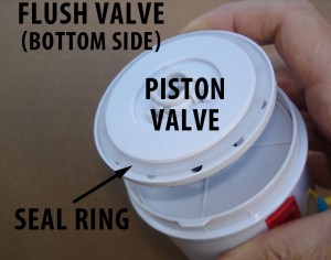
2) The piston seal ring in the flush valve is not sealing properly due to a problem with seal itself or the base lip it seals against.
3) The black tank gasket at the base of the flush valve at the tank drain is not sealing.
To determine which one of these problems is causing the leak, simply turn off the water at the wall spigot and wait to see where the water level settles . . .
If the water leaks down to level of the outer overflow tube, then that is the problem. Pull the inner overflow extension all the way out, check the o-ring seal, put some silicone grease on it and replace it. Check the water level in the tank with respect to the overflow tube and make sure that overflow tube is adjusted high up enough to prevent leaking, usually about an 1 or so above the water line and below the hole or holes where the bowl fill tubing enters (if applicable).
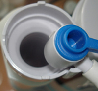
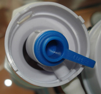
If water leaks down to the level of the piston valve, then it may be that the base lip has a defect in the plastic or debris built up on it or it could be a problem with the silicone seal itself. Simply twist out the flush valve from its base and carefully inspect the base lip where the piston valve mates to it. Run you finger around the circumference of the base lip to make sure it is nice and smooth, checking for any irregularities or debris.
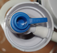
Then inspect the seal ring around the piston valve. Clean off any debris and check the surface of the seal ring to ensure that it does not have any pitting, bubbles or irregularities. If any problems are found, carefully remove the seal ring by working it out and over the piston. It is made from a strong silicon rubber and will not tear easily, but take care not to stretch it anymore than necessary for removal or else it could become deformed. Check the other side and if that side is in good condition, simply flip it over and reinstall.
Note that we sell all sizes of replacement piston seal rings should it need to be replaced for any reason . . .
When replacing the seal ring, warm it up in hot water for a few minutes, apply a thin layer of silicon grease (optional, but recommended) and work it back over the piston, again taking care to not stretch it any more than necessary when installing.
Once everything looks good, align and twist the valve back into its bayonet mount while checking to ensure it is fitting squaring down into the base. Before turning the water back on, operate the flush handle or push button and make sure that the piston valve is dropping down freely and securely into the base lip.
Refill the tank and if the level holds, then the problem is solved, but if the tank is leaking down all the way to the bottom, then continue . . .
Once the overflow tube height and piston valve seal is confirmed, the only other area to check is the seal on the base of the flush valve at the tank drain. Remove the tank and flush valve base, then carefully inspect the gasket for any irregularities and the mating surface area on the tank drain for any nicks, roughness or debris. If any problems are noted that are not easily corrected, then simply run a bead of clear silicone bathroom chalk under the gasket lip before reinstalling.
Now check the size of the drain hole as compared to the size of the flush valve fitting to make sure there is adequate gasket over lap for a good seal over the tank drain. Usually 1/16″ to 1/8″ clearance around the circumference yields plenty of gasket overlap and much beyond that requires the addition of our shim washers – SEE HERE. Once everything is inspected and prepared as required, reinstall the valve base, center it in the drain hole, push down on it by hand and then tighten the flush valve base nut as tight as possible, also by hand. It is not possible to over tighten by hand and it should be just tight enough to slightly deform the gasket, but not so tight as to over compress it. Usually, firm hand tightening while pressing down on the valve base from inside the tank is enough, but add another quarter to half turn with a large wrench if the gasket is not compressing enough by hand.
Before reinstalling the tank, test all the seals by simply placing the tank over a large bucket (5 gallon paint bucket works well), fill it with water, add a little food coloring and watch for any leaks into the bucket. Pin down the leak by noting the area where the colored water appears and readdress the possible leak sources as explained above.
#5 EasyFit Drop-In GASKET LEAKS
In order to ensure a tight seal between the EasyFit valve and the flapper base, it is VERY IMPORTANT to ensure that the flapper base lip is clean and smooth. Also check the GREEN EasyFit gasket for any irregularities or debris and make sure it is warm enough to be soft and pliable when installed. If not, simply soak the gasket in warm water for a few minutes. Then rotate the gasket as required until it aligns and mates squarely with the slope of the flapper base lip as shown in the Installation Instructions.
If any leaking occurs anytime after installation, remove the valve, inspect the gasket again for any irregularities or debris, warm up and replace, again ensuring that the gasket is rotated to properly mate with the flapper valve base and that it is well seated and secured.
When properly installed, seated and tightened down on a clean flapper base, the EasyFit gasket seal WILL NOT LEAK.
For more detail, see our installation video over on the “Instruction Videos & FAQ” tab.
#6 VIBRATION, CLICKING or SHUDDERING SOUNDS
There is a common and harmless physical phenomenon in plumbing known as “air hammering”. This occurs when an air bubble gets trapped somewhere in the lines, spigots or plumbing fixture that causes a gentle resonance, like the vibration induced in a wind instrument. Air can easily get into any plumbing system during an install and can also originate anytime from tiny pinholes in the pipes or from the hot water heater, particularly if the water temperature is very high.
Usually, the bubble will work itself out in time or try adjusting the wall spigots to change the pressure and possibly reduce or eliminate the resonance. If the noise persists and/or is particularly annoying, try using a longer or shorter flex line from the wall spigot to the fixture to dampen the resonance. It is also possible to fully purge the lines by removing them from the fixture and running the water into a bucket for a period of time, but that is often cumbersome to do and ineffective if the bubble is permanently trapped or just keeps recurring.
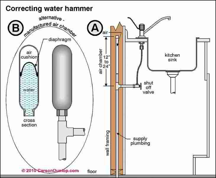
There is also a similar phenomenon that results from the physics of the length and routing of the plumbing to a fixture known as “water hammering”. In this case, the entire end-to-end plumbing is like a long string on a string instrument and unfortunately happens to be just the right length to vibrate like a string on an instrument as well. So anytime the water is flowing, it provides the “plucking” energy to the “string” and hence the noise.
Often, neither water hammering nor air hammering can be completely eliminated due to the inherent physics of the plumbing system or the fact that air is continuing to get in. So it’s just part of normal house noises that can occur over time or anytime a plumbing change is made and is really nothing to worry about.
However, for more extreme hammering problems, there are methods and products outside the scope of DIY repair that a plumber can recommend and install that are often very effective, though somewhat involved and costly.
See the pic below for common examples . . .
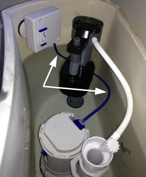
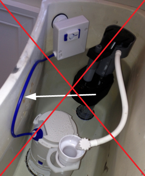
#7 ERRATIC FULL or HALF CYCLES - POOR CABLE ROUTING
The single most common cause of flush problems is the cable routing. Since the flush mechanism is a very lightweight system, the cable must be routed in a nice lazy arc from the flush valve over to the flush handle or push button. It only takes a very slight cable binding to prevent the mechanism from functioning properly, so if the cable is curved too much or flexed up against the tank wall or other component, it will bind enough inside to keep from moving freely enough for a smooth cycle.
IMPORTANT: The quickest and easiest way to determine whether or not the cable is routed properly is to hang the cable box up over and outside the tank such that the cable is roughly in a straight line to the flush valve. Then depending on the kit type, reinsert the lever, push button or just a screwdriver and try a few test flushes. If all is well, then reinstall the cable box and reroute or reposition the cable box and cable routing as required.
Also note that in some cases, the cable may have some residual bend to it from the shipping carton and if so, simply straighten it out by pulling the cable through your fingers against the curve, especially right at the cable box and valve entry points.
In other cases where the unit has aged significantly or the water has large mineral or chlorine content, then the cable may bind over time due to eventual contamination. This can be remedied as well by disassembling the cable box and spraying in some CRC 2-26 (available at Home Depot) or other plastic-safe lubricant.
DO NOT USE WD-40 OR OTHER STANDARD PETROLEUM LUBRICANTS AS THEY CAN DAMAGE THE PLASTICS.
#8 FLUSH HANDLE or PUSH BUTTON STICKS
If the unit is brand new, first make sure that the cable is routed properly and not binding as explained in #7 above. If not, simply work the lever or push button a few times during a flush cycle to break in the mechanism and make sure it is not sticking somewhere within the actuator itself. Do this with the water turned off or during a flush cycle and before the tank fills to make it easier.
If the unit is older, first check to make sure the cable routing still looks good and that the bend radius has not started to tighten up. If so, reposition it and/or pull it through your fingers and against the curve to widen the bend. Be sure to check right at the cable box and valve connections as well. Refer to #4 for more info on cable routing.
The next most likely cause is mineralization build up or other debris inside the actuator box or cable. Remove the flush assembly, dismantle the cable box and inspect for debris or mechanical damage. If debris is found to be clogging the inside actuator mechanism, simply clean it out and/or soak in vinegar, CLR or other descaling solution (available at Home Depot).
Then lube with a plastic-safe spray (such as CRC 2-26 also available at Home Depot or Amazon) and reassemble. If the unit is found to be damaged inside, see our parts section for a replacement valve.
#9 PISTON VALVE STICKS and FAILS TO DROP
If the unit is brand new, first make sure that the cable is routed properly and not binding as explained in #7 above. Then simply work the lever or push button a few times with the water turned off or during a flush cycle to break in the mechanism.
If the unit is older, first check to make sure the cable routing still looks good and that the bend radius has not started to tighten up or kink at the end points. If so, reposition it and/or pull it through your fingers and against the curve to widen the bend. Be sure to check right at the cable box and valve connection endpoints as well. Refer to #4 for more info on cable routing.
The other mostly likely cause is mineralization build up or other debris inside the actuator box, cable or flush valve itself. Remove the flush valve assembly from its base and soak the whole thing in vinegar, CLR or other plastic safe descaling solution (available at hardware stores).
DO NOT SOAK FOR MORE THAN 15 – 20 MINUTES OR THE PISTON SEAL WILL START TO DEFORM.
If the problem persists after soaking, dismantle the cable box (some are sealed and cannot be opened) and inspect for debris or mechanical damage. If debris is found to be clogging the inside actuator mechanism, simply clean it out and/or further soak in vinegar, CLR or other descaling solution. Then lube with a plastic-safe spray (such as CRC 2-26 also available at hardware stores or online) and reassemble.
If any damage is found or the piston valve continues to stick, we sell the top valve assembly (valve and cable box) separately for quick and easy replacement at low cost. See our Parts section for replacement top valves.
#10 FLUSH HANDLE or PUSH BUTTON NOT HOLDING
If the flush handle or push button does not hold on it own during a flush cycle and has to be held manually, the problem is either a cable routing/binding problem or the height of the water level above the valve is not sufficient for the flush floats to hold.
Refer to FAQ #7 above to ensure that the flush mechanism is not binding due to a cable routing problem.
Then adjust the tank filler valve to raise the tank water level up higher over the top of the valve to increase the pressure on the flush floats. This will not increase the amount of water used per flush, but will simply increase the water pressure on the floats and enable them to lock and hold the flush mechanism.
#11 FLUSH HANDLE CLEARANCE and POSITIONING
Depending on the orientation of a given flush handle mount with respect to the seat lid and tank lid, the flush handle may interfere with one or both.
If the seat lid hits up against the handle when raised, simply install a standard stick-on rubber bumper at the point of the contact with the tank or tank lid to hold the seat lid out far enough to prevent further interference.
Then if the location of the flush handle in relation to the tank lid prevents it from swinging up far enough to engage the UP flush cycle without hitting the edge of the lid, there are two options: The first is to reposition the handle pointing downward for a left-right flush orientation. Many dual-flush users prefer this orientation anyway because it helps to remind them of the dual-flush feature. It may seem a little odd at first, but quickly becomes the new normal with use.
Another option is to replace the flush handle mechanism with a push button instead. With our EasyFit Drop-In kits, the flush handles and push buttons are interchangeable, so it’s very easy to swap them out. With our other kits, the flush mechanism is integrated into the flush valve, so the valve assembly itself has to be swapped from its base. This is also fairly easy to do because the valve simply rotates and comes free from its base without tools and without removing the tank.
#12 FLUSH HANDLE INTERCHANGING
Each flush handle type is matched to its specific flush valve and cannot be interchanged with other valves. This is because the flush mechanism is a very light weight system, so the flush handle has to be precisely weighted, balanced and spring loaded (in some designs) to match the mechanics of its respective valve.
For more advance installers, we do sell all flush handle types separately and it is certainly possible to modify any flush handle to fit any other valve. However, those types of modifications are somewhat complex and beyond our scope of support.
#13 SWAPPING LEVER HANDLES and PUSH BUTTONS
It it not possible to simply swap a Lever Handle for a Push Button or vice versa, because the cable boxes and mechanics are DIFFERENT. The Lever Handle has a rotational mechanism, while the Push Button version has a linear mechanism, so the valve itself must be replaced. However, in most cases, the valve BASE is universal, such that only the valve HEAD needs to be replaced, which is quick and easy. Simply twist the valve head out of its base and replace, no tank removal required. A basic valve assembly for most kits can be purchased in our Products section – check with us prior to ordering to ensure compatibility with your particular kit.
One exception is our EasyFit DropIn series of kits, where the cable box on the valve is UNIVERSAL and will accept either the Lever Handle or Push Button actuator as desired. Simply remove the existing Lever Handle or Push button actuator, rotate the cable box 90 degrees to the other socket and replace with the desired actuator. See our Parts section under the Products tab to purchase individual Lever Handle or Push Button actuators.
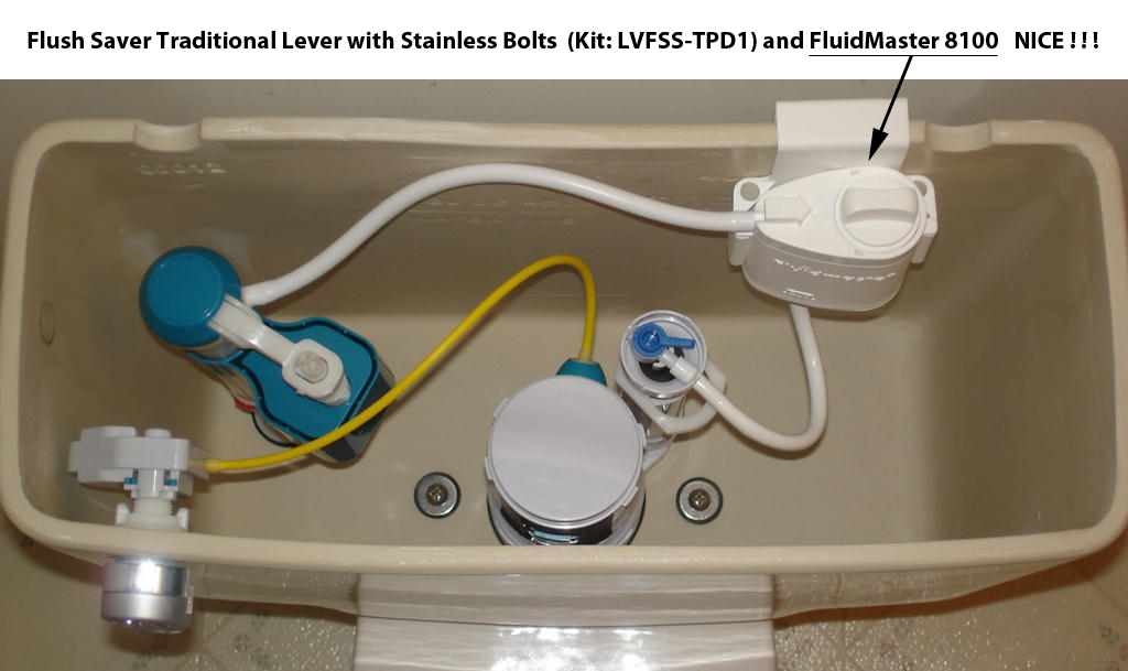
#14 BEST AUTOMATIC CLEANING SYSTEMS
The problem with most automatic toilet cleaning products that originate in the tank (either liquid or cake) is that they damage the various seals over time and quickly waste away in the tank water. Bowl cakes are better because they aren’t in the tank and don’t deteriorate the tank seals, but still tend to waste away quickly with the flush water. So the best option is a cleaning system that feeds from the bowl fill valve directly ino the bowl, such as the Fluidmaster 8100 Flush ‘n Sparkle.
We do not represent or sell Fluidmaster products, but this one works great with our flush kits, is easy to install and ends up lasting a long time and costing less.
#15 FlushMinder SETUP and TESTING TIPS
HOW TO ORDER PARTS
We sell ALL parts for the flushMinder and ANY Flush Kits for a REASONABLE LOW COST, but there are way to many to list. Simply email us on which part you need and we will send you a buy link . . . that simple and nothing to look up.
Note that the Motor Mount is easily broken if twisted or mounted askew, so we will replace it for just $1 + minimum USPS First Class shipping cost. To prevent future problems, carefully mount the motor into position and run a bead of super glue or epoxy along the seam to hold it permanently.
Order the replacement Motor Mount CLICK HERE . . .
DETECTION SENSOR MOUNTING and CALIBRATION
The included sensor cable is 22″ long which is plenty of length for mounting it right above the toilet tank as described in the instructions. However, it is a standard 30 gauge 4 wire cable that can be extended by splicing with phone or USB cable up to about 6 feet. Note that it does not matter where the sensor is actually located with respect to the toilet just so that it can detect the person within the specified range.
Each sensor is precisely calibrated and tested before shipment to detect a human presence in the range of 0 – 31.5 +/- 4.0 inches (80 +/- 10 cm) as stated in the Specifications block of the Installation Instructions. If the detection distance is less than this amount after calibration or later in time, replace the batteries with a known good fresh set and recalibrate as explained below.
Be sure to mount the sensor above and behind the toilet tank or to one side such that the distance from the sensor to the person is within this range and that no other objects are inside of this range or any reflective objects (like a mirror) are anywhere in front of the sensor.
SENSOR MOUNTING FOR CATS
If setting up for cats, it is usually best to mount the Sensor right on front of the toilet tank or seat lid or on a side wall if close by. However mounted, the Sensor needs to be fairly close to the cat to detect and that may require some observation and experimentation depending on cat size and potty habits. For some installations and cats, it may be desirable to actually NARROW or REDUCE the detection range, see the DETECTION RANGE and SENSITIVITY ADJUSTMENTS paragraph below.
CALIBRATION PROCEDURE
To reset the unit and activate the calibration cycle, simply remove the batteries, wait 30 seconds, reinstall the batteries and IMMEDIATELY hold the unit by hand in its mount position while standing to the side out of the detection beam until the Detection LED stops flashing. Another option is to lay the flushMinder on its back (face up) toward the ceiling and step away.
Either way, take care not to block the Detection Sensor with your hand or to have anything in front of the unit within 4 1/2 feet as stated in the instructions.
IMPORTANT: Continue to hold the unit IN PLACE and VERY STILL until the LED stops flashing or the detection range will be very short. If the detection distance is not correct, simply remove the batteries and try again. If the detection is still not calibrating correctly, then replace the batteries with a known good fresh set and repeat this process.
Now replace the battery cover and mount the unit on its wall mount. Note that a flush cycle or 2 may activate during mounting, so either temporarily remove the lift chain or otherwise just be prepared for the flushes.
Also note that the sensor is not a “motion detector” but a human presence detector, meaning you need to be in front of it with the Detection LED flashing for over 10 seconds to get a half flush and over 60 seconds to get a full flush. Those are typical times at the toilet to determine the #1 and #2 flush cycles. Just waving a hand in front of it will simply cause it to detect briefly and then reset without activating a flush cycle.
ACTUATOR MOUNT INSTALLATION
The actuator mounting collar must be attached securely to the bowl fill (overflow) tube of the flapper base assembly for the flush cycles to work properly. Otherwise, the actuator will rock downward toward the flapper when the lift lever pulls on the chain, reducing the range of motion and resulting flush volume.
Depending of the outside diameter of the overflow tube, the mounting collar may clamp on tightly by itself or may require the additional of one of the two sizes of silicone adapters included with the kit. In some cases where the overflow tube is too large for either of the adapters, but not quite large enough for the collar to clamp down securely, then simply add enough wraps of electrical or similar tape to get the desired fit. It also possible to reduce the diameter of the adapters by slitting them open and trimming down the ends and inside ridges as required.
FLUSH CYCLE SETUP
Use the magnetic wand to set the Half Flush cycle time by increasing or decreasing the lift time on the flapper valve. Hold the wand against the circular target on the sensor unit (right side) and watch as the lift motor cycles up about 1/2 way, then quickly remove the wand. Try this a couple times to get the idea of the lift motor timing and to get the amount of flush water desired for a #1 Half Flush.
The Full Flush cycle time will be set automatically in relation to the Half Flush time.
Note: If only the Full Flush cycle is desired, then simply set the Half Flush all the way up with the magnetic wand. That will make both cycles the same Full Flush regardless of the “time at the toilet”.
FLUSH MOTOR AND BEAD CHAIN ADJUSTMENT
The flush motor lever either cycles up within the limits previously set in the Half Flush above step or to the maximum range for a Full Flush and then right back down again in one smooth motion. If the flapper is not lifting high enough and long enough for the desired flush cycle, simply reposition the bead chain to increase the amount of lift height on the flapper and then increase the Half Flush time with the magnetic wand.
Do not allow the flapper to lift too high or else it will pop fully open and defeat the reduced flush cycles. The flapper should lift just high enough and long enough for the desired flush cycle, but not fully pop open as it does with the flush handle.
If the flapper is popping fully open or the motor is binding due to excess load, simply reposition the bead chain a little more loosely to reduce the lift height.
Note: To test the flush motor servo for proper operation, simply remove it from the tank and observe a Full Flush cycle. If the full range is achieved outside the tank, then simply reposition inside the tank for the right balance of lift height on the flapper.
FLUSH TESTING
Each flushMinder is thoroughly tested on a powered test set with weights attached to the lift lever of the actuator motor to ensure proper detection and lifting power. However, the batteries shipped with each unit are not tested, so a bad one can get through or one of more of the batteries can be improperly installed and not making good contact.
The unit can be manually tested anytime by simply holding the actuator in hand while standing in front of the detection sensor for a good minute or more, which will then trigger a full flush right after the stepping away and out of the detection range.
During the detection time, make sure the detection LED flashes consistently the entire time (the center LED). Then hold and observe the actuator motor move the lift lever upward from about 90 degrees to about 130 degrees against hand pressure on the lift lever with reasonable force, meaning enough force to lift the flapper valve. To get a better idea of how much force is required to lift the flapper, just pull up on the chain that connects from it to the flush lever down inside the tank. If the detection LED is not constant or the actuator motor does not move the lift lever with enough force, carefully check all 6 batteries for good contact or try a whole new fresh set.
Once the detection and actuator motion functions are tested and confirmed, it’s just a matter of making sure the installation down inside the tank is done properly. That includes making sure the motor mount is firmly attached to the overflow tube and there is minimum slack in the bead chain. Once the lift lever starts to pull on the flapper, the actuator motor should hold firm and not bend or twist toward the flapper as that will naturally reduce the amount of lifting motion on the flapper and in turn, reduce the amount of water released during the flush.
After confirming the detection, actuator motor force and actuator mounting, the flushMinder will flush properly when installed on a standard-sized toilet tank with the water level set to the factory water line.
For smaller non-standard tanks or tanks with a lower water levels, the full flush may work properly, but the half flush cycle may not provide enough water volume to satisfactorily evacuate the bowl. In that case, simply use the magnetic wand in Step 5 to increase the half flush volume all the way up to the same as the full flush.
If there is still not enough water released for either cycle, then we offer extended lift levers (Click Here) or the length of the standard lift lever can be increased by simply attaching a little piece of coat hanger or similar wire to it with cable ties. Bend a little hook shape at the end of the wire and attach the bead chain to it securely with another cable tie. That will increase the lifting range and insure that enough water is released. Be careful not to extend the lift lever too much or excessive water will be released and wasted, so adjust the lever length accordingly to get a good flushes, but not a lot of excess.
FLUSHMINDER PRODUCTION TEST SET
Each flushMinder unit is fully tested for ranging and lifting power with multiple cycles . . .

DETECTION RANGE and SENSITIVITY ADJUSTMENTS
In order to keep the sales price of the flushMinder as low as possible and to greatly simplify the installation process for the average user, neither the detection range, sensitivity, nor flush cycle timing are programmable beyond the half flush volume amount, set with the magnetic wand in Step 5 of the instructions. The fixed settings for these parameters have been extensively researched and found to be optimal for most user and bathroom environments. However, there are several ways and workarounds to address installation issues with the detection sensitivity and ranging:
Once the calibration step is done correctly and completes, the average human detection range is set to approximately 34 inches. The actual detection distance of other objects (or cats) will vary depending on the size of the object placed in front of the detection eye. Smaller objects, like a hand, have to be fairly close, while larger objects or walls can be detected another 12 – 18 inches out. The MAXIMUM detection range can be optimized but not increased, as that is a fixed design parameter. But it can be NARROWED or REDUCED, which may be desirable for some cats or for installations only requiring timed flushes.
For MAXIMUM detection range and accuracy, the flushMinder sensor needs to be positioned such that the user remains inside the detection area until completely finished without moving in and out of the detection area and causing multiple flushes. This can take some trial and error with the positioning depending on how the user enters the bathroom, uses the toilet and then exits the room. The sensor also needs to have a clear view of the user at all times with no large obstructions within approximately 48 inches and no mirrors behind or close by.
To NARROW the width of the detection range, the diameter of the flushMinder detection area can be reduced by attaching a short collar or cone around the detection eye. This cone can be fashioned out of any thin plastic or card board and the sizing adjusted to suit the desired detection area.
To REDUCE the detection range, place a piece of transparent or translucent cellophane material over the detection eye window. Most any colored cellophane will work and the sensitivity can be adjusted lower and lower by simply stacking more layers to darken the incoming light. Note that another calibration cycle may be required after attaching the cellophane.
To GREATLY REDUCE the detection range down to below 12 inches, simply run the CALIBRATION PROCEDURE above “incorrectly” by placing an object in front of the detection eye (or point it toward a wall) within 1 – 2 feet.
These adjustments require some trial and error plus some extra installation work beyond the usual process of course. But in most all cases, customers report being successful in getting their FlushMinder to work satisfactorily with kids, the elderly, disabled, persons with special needs and of course cats of all types and sizes, in bathrooms of all shapes and sizes.
MANUAL FLUSHES
If the FlushMinder does not detect and flush for any reason or an extra flush is required at any time, the toilet can always still be manually flushed with the lever handle as before.
AUTOMATIC WEEKLY FLUSHES
The FlushMinder is programmed to automatically activate one full flush per week if no previous flushes have occurred. The weekly flush ensures that the toilet bowl is kept full of water and fresh if there is is no usage during the preceding week. This is particularly useful in vacant apartments or office buildings where the water in the bowl could dry up and allow noxious sewer gasses to escape.
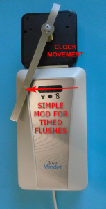
ADDITIONAL TIMED FLUSHES
Other than the automatic weekly flush described above, there is no further option for programming additional scheduled flushes because that would overly complicate the FlushMinder setup process for most users and make it much more costly to manufacture. However, it is fairly easy to add a basic clock module to activate one more automatic flushes per day. Simply attach the clock module to the top of the detection head with double-sided tape, positioned such that a sweep hand or hands attached to the hour shaft can pass over the detection eyes and activate the flush or flushes as desired. These types of basic clock modules have long battery life, are very inexpensive and readily available at local craft shops or online.
Once configured with the clock module, the FlushMinder will flush either when it detects a person or when the sweep hand or hands passes over the detection eye. To disable the person detection and only use it for timed flushes, simply turn the detection head away from the person or up toward the ceiling. It is also possible to reduce the detection range by simply doing the calibration step “incorrectly” by pointing the detection head toward the wall a foot or 2 away, instead of toward clear space as explained in the CALIBRATION PROCEDURE above.
See the example pic below . . .
BACKPLATE DOUBLE-SIDED FOAM TAPE REMOVAL FROM WALL
To remove the backplate from a wall without damaging the paint, take a cheese cutter or length of fine wire and cut down through the tape between the backplate and the wall. Once the tape is cut all the way through, remove the blackplate and then wet down the remaining foam tape with Zippo or Rosonol lighter fluid. Let it soak for a few minutes and then gently peel away the tape with a fingernail or plastic scrapper. Now wipe off any excess adhesive or lighter fluid with a paper towel dampened with lighter fluid and let it dry. There may be some brief discoloration of the paint from the lighter fluid initially, but that will disappear once it evaporates. If this procedure is done slowly and carefully, the backplate foam tape (or any foam tape) can be removed without a trace of damage to the paint.
CANISTER VALVE FITTING OPTIONS
The flushMinder actuator motor mount is designed to fit on top of the bowl fill (overflow) tube of a standard flapper valve. Overflow tubes commonly have an outside diameter range of 1 to 1 1/2″ and the actuator mount will clamp onto that size range firmly using the included silicone collar adapters as required.
For toilets equipped with canister valves, the flushMinder actuator configuration will not work without either doing a further addition or changing it out for a standard flapper valve.
The addition required would be adding a piece of PVC or similar tubing to the side of the canister valve with cable ties. The outside diameter of the tubing needs to be around 1 to 1 1/2″ so that the actuator mount can be attached to it firmly, like it would be to the overflow tube of a standard flapper. It’s also fine to just cut off the overflow from an old flapper valve base and use it.
Then connect the bead chain from the actuator to the lift lever of the canister valve.
That approach can take some time and get a little tricky, so an easier way is to just remove the canister valve and convert it over to a standard flapper, which is the more common solution.
Standard flapper valves are readily available, inexpensive, easy to change out and will ensure the actuator can be mounted securely and work properly.
#16 BootySaver LOW NOZZLE SPRAY VOLUME
If the unit is freshly installed or still fairly new and the nozzle spray volume suddenly drops, then there is some kind of debris or other obstruction clogging the nozzle or one of the water lines. See UNIT PURGING below . . .
If the unit has been in use for a while and the spray volume starts to decrease or the spray pattern starts to change slowly over time, then there is a blockage due to mineral buildup in the nozzle orifice. See ORIFICE CLEANING below . . .
ORIFICE CLEANING
First check for a white chauky mineral build up on or around the nozzle orifice. The nozzle retracts into its outer sleeve when not is use, but can be extended out by turning on the water, catching it in hand and then turning the water back off. It can also be pulled out with a bent paperclip inside the orifice, but BE CAREFUL NOT TO ENLARGE OR OTHERWISE DAMAGE THE ORIFICE.
If mineral deposits are found, simply soak the nozzle in a cup of white vinegar or other demineralizer such as CLR to dissolve them off. A soft brush can also be used to speed up the process.
If no mineral deposits are found, then there is some kind of debris or obstruction inside the nozzle or one of the water lines. See UNIT PURGING below . . .
UNIT PURGING
Purge the nozzle and lines by fitting a suitable piece of tubing over the orifice and forcing air or water back through the unit either by mouth, with a shop vac blower or other source of compressed air. Repeat this process with the Temperature control set at both extremes to ensure that both lines are fully cleared.
#17 flush n’ Clean INSTALLATION and USAGE TIPS
CONNECTION TUBING: Each flush n’ Clean unit comes with two pieces of thick wall clear tubing. Either can be used for the in or out connection as desired for the best fit. If longer tubing is required, any hardware or pet store aquarium tubing will work fine. Also, if the existing tubing is in good shape, it can simply be reused along with either one of the other pieces. Warm the tubing ends in hot water if required for more stretch on tighter fits.
BROMINE TABLETS: Due to the continued stock piling of sanitizers, bromine tablets may a little difficult to find at times, but are generally available at most hardware, big box and pool supply stores or on our website sold in convenient inexpensive 6 packs.
The diameter of the bromine chamber is 1 1/8″ to easily fit and accommodate standard 1″ tablets. Our preferred source and the ones we ship with the flush n’ Clean unit are the Leisure Time brand which come in small diameter low powder pellets. Some of the other tablet brands on the market today that are labeled as 1″ are actually more like 1 1/4″ (most notably Leslie’s) to allow for chipping and shrinkage. Those larger tablets can still be used by simply chopping them in half or smaller like a pill. The size or shape of the bromine is not important . . . just add in enough pieces to fill the chamber about 1/2 inch from the top.
CHLORINE TABLETS: Either bromine or chlorine tablets can be used interchangeably, but bromine is recommended because it is less harsh and produces almost no smell. Chlorine does tend to be less expensive and is usually more readily available, but it will have that pool chemical smell and will also reduce the life of the tank components somewhat.
PERIODIC INSPECTION: Depending on frequency of toilet use, check the bromine chamber every few months or so and refill as required. Also inspect the tubing and tubing connections for any leaks or cracks due to aging. ALWAYS CHECK FOR LEAKS BEFORE REPLACING THE TANK LID ! ! !
BROMINE or CHLORINE DISSOLVING TOO QUICKLY: If the tablets are found to be dissolving too quickly, as in weeks vs months, check the following:
1) Note the amount of water flow from the filler valve through the flush n’ Clean unit and into the bowl filler / over flow tube. There should be just enough water going through to refill the bowl with each flush cycle and no more. Once the bowl is refilled, any additional water is just further dissolving the tablets and is wasted down the drain. Simply adjust the bowl filler valve down to a trickle and just enough to refill the bowl.
2) Make sure that the top vent is not clogged and that the lower tube is routed as shown in the instructions to ensure that most of the water drains down from inside the Flush n’ Clean unit after each flush. The lower fitting on the flush n’ Clean (outlet side) should be approximately level with the bowl filler valve at the bowl fill / overflow tube for the water to drain down. If the water does not drain down somewhat, the tablets will remain in that standing water and dissolve quickly. Simply adjust the tank water level and bowl fill / overflow tube down as required to approximately match the height of the Flush n’ Clean outlet nipple.
3) Test the pH of the water with pool pH strips to ensure it is around 7. Anything less than 7 indicates that the water is acidic which will accelerate the tablet dissolve rate. The only remedy for acidic water is have a whole house water treatment system installed which would be beneficial for the overall plumbing system, but may not be practical. However, this simple test would at least identify whether or not the water pH is part of the problem.
BROMINE or CHLORINE DISSOLVING TOO SLOWLY: If the tablets are found to be dissolving too slowly, as in many months, check the following:
1) Note the amount of water flow from the filler valve through the flush n’ Clean unit and into the bowl filler / over flow tube. There should be enough water going through the system to flush out the bromine solution and refill the bowl with each flush cycle. Simply adjust the bowl filler valve to increase the water flow enough to thoroughly flush the bromine chamber and refill the bowl.
2) Another option is to break the bromine tablets into smaller pieces to increase the surface area and hence the bromine concentration.
3) Test the pH of the water with pool pH strips to ensure it is around 7. Anything greater than 7 indicates that the water is too alkaline which will decrease the tablet dissolve rate. The only remedy for alkaline water is have a whole house water treatment system installed which would be beneficial for the overall plumbing system, but may not be practical. However, this simple test would at least identify whether or not the water pH is part of the problem.
4) A significant benefit of the flush ‘n Clean over other similar products is the top vent that drains out the water and prevents over dissolving of the bromine tablets. But if more bromine concentration is desired, simply close off the vent with super glue gel or epoxy. Closing the vent will leave some water inside the bromine chamber after each flush and create a stronger bromine solution for the next flush. This modification is fine for higher use toilets that are flushed frequently, but not so much for lower use toilets where the tablets can be over dissolved and wasted.
TOP VENT WATER SEEPAGE: The purpose of the vent is to allow the flush n’ Clean to completely fill and then drain down during a flush. In some cases, the ball float inside may not seal completely and dribble a bit of bromine solution into the tank which is common and not a problem.
When first installed, some may even leak out quite a bit at first but that should subside as the ball valve inside swells and seats.
However, if there is still too much water coming out the vent, then just turn the water pressure down at the spigot to the toilet and/or increase the water out of the flush n’ Clean to the overflow / bowl filler valve. In other words, just restrict the water to the flush n’ Clean or increase the water out of the flush n’ Clean.
Most toilets have the water pressure turned up way too high anyway, which puts undue strain on the filler valve and makes the refill cycle unnecessarily noisy. The spigot pressure should be adjusted for a good balance between reasonable refill time and yet fairly quiet operation.
Over time and depending on the water conditions and type of cleaning agent used, the ball valve inside the vent can stick or deteriorate and begin to increase the amount of water released. The top vent is not critical and can simply be closed off with a couple drops of super glue if too much water is coming out of it or if no venting is desired.
We are also happy to offer a discount coupon to any return customers wanting to purchase new flush ‘n Clean units. Simply contact us with the previous order number for details.
Helpful Installation Pictures
Here are some illustrations and installation pictures of different toilet configurations from DIY installers all around the country. Please send us your own ideas and pics to share with others as well.
Please note:
You can also find the installation manual for any of our products on the order pages and there is also a wealth of information to be found online by searching “dual flush”.
If you can’t find the solution to your problem here, no need to struggle further or be frustrated as you can contact us directly at the link below and we will provide the assistance you need: